
LISA: building a gravitational-wave observatory across space
LISA links free-falling test masses through laser measurements. Telescope prototypes, charge control and simulated data mark separate steps toward flight.
The European Space Agency approved the Laser Interferometer Space Antenna, or LISA, on Jan 25, 2024. The adoption cleared the mission to proceed toward instrument and spacecraft construction. Three spacecraft will follow Earth around the Sun, exchanging laser signals across a triangular formation with sides 2.5 million kilometres long. Pairs of gold-platinum test masses will float freely inside the spacecraft. Their changing separation provides the gravitational-wave measurement. ESA leads LISA with NASA and an international scientific consortium; launch was planned for 2035 aboard Ariane 6. ESA lead project scientist Nora Lützgendorf identified the mission's enormous laser distances and instrument stability as the route to frequencies inaccessible from the ground. Targets include merging massive black holes and compact binaries in the Milky Way. The mission approval preceded several further years of development.
From mission approval to industrial construction
ESA and OHB System AG signed their agreement to build LISA at the Paris Air Show on Jun 17, 2025. OHB became the industrial team's leader, working with Thales Alenia Space. The next activities included finalizing the spacecraft design and beginning construction with the scientific team. These industrial responsibilities sit within a wider collaboration among ESA, its member-state agencies, NASA and the LISA consortium. ESA's responsibilities include the spacecraft, launch, mission operations and data handling. The planned contributions assign the free-falling masses to Italy and Switzerland, while Spain is responsible for the Science Diagnostics Subsystem. Signal-detection contributions from other member states complete this division of the instrument work.
National contributions cover several different parts of the measurement system. The free-falling masses need protection from external forces; optical metrology must extract an exceptionally small signal; diagnostic sensors track conditions elsewhere in the spacecraft. The main hardware groups include:
- Test masses and their shielding.
- Interferometric signal-detection systems.
- The Science Diagnostics Subsystem's spacecraft sensors.

Telescopes for transmitting and receiving laser light
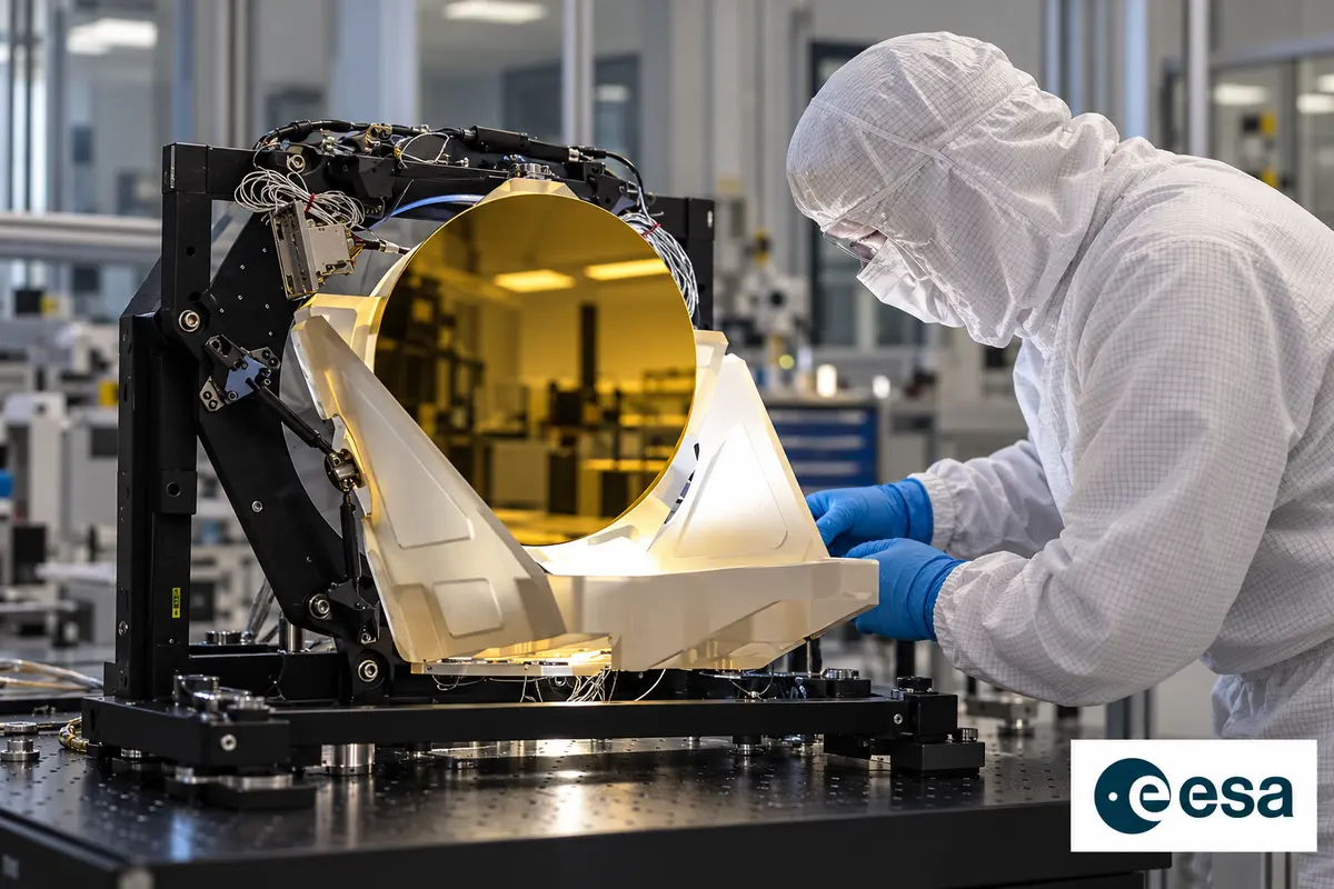
The first full-scale Engineering Development Unit Telescope arrived at NASA's Goddard Space Flight Center in May 2024. L3Harris Technologies manufactured and assembled it in Rochester. On May 20, technicians moved the unit, still in its shipping frame, within a Goddard cleanroom. The prototype supports development of six flight telescopes. Each LISA spacecraft will carry two, with each telescope transmitting and receiving infrared light along one of the observatory's long arms.
The prototype uses Zerodur, an amber-coloured glass-ceramic made by Schott in Mainz. Its dimensions change very little over a wide temperature range, a property useful for precision optics. A gold coating on the primary mirror improves infrared reflection and reduces heat loss from the surface exposed to cold space. The telescope performs best near room temperature. Material stability and thermal behaviour therefore accompany the task of collecting a distant laser signal, rather than simply maximizing the size of an astronomical image.
A later unit prepares the route to flight
By October 2026, L3Harris was preparing another telescope stage for NASA: the Engineering Test Unit. The company would design, assemble and integrate the all-glass unit before future production of flight hardware. NASA's telescope programme lead, Ritva Keski-Kuha, identified it as the last pre-flight unit and the first planned optical telescope delivery to ESA. The earlier engineering-development prototype had already undergone testing whose results would inform this next telescope.

A structural model delivered in June 2026 used metal rather than glass. Its delivery and the forthcoming optical test unit were separate steps, with different materials and purposes. The 2024 prototype, the metal structural model, the Engineering Test Unit and eventual flight telescopes therefore occupy distinct positions in the development sequence. The spacecraft's final complement of telescopes remained a future delivery; neither the existence of a prototype nor a structural-model handover amounted to deployment of the observatory.
Keeping the free-falling reference electrically quiet
Each gravitational reference sensor surrounds a test mass with an electrode housing that measures its position and orientation. Feedback drives the spacecraft's thrusters so that the surrounding vehicle follows the mass. The masses provide local inertial references and the endpoints of the interferometric measurements. LISA's target frequency band extends from 0.1 millihertz to 1 hertz. Within this measurement system, charge acquired from the space environment can produce unwanted forces and acceleration noise.
Ultraviolet light can discharge a mass through the photoelectric effect. Charge-control simulations published on Feb 17, 2025 examined pulsed UV LEDs synchronized with an existing 100-kilohertz electrical field. The synchronization controls the direction of photoelectron current, while duty cycling can reduce required light power. Modelling tracks charge movement and its force-noise contribution under a deep-space radiation environment. A University of Florida torsion pendulum offers a ground-based route for testing such simulations; validation in the actual flight environment must await the mission.

Delivering ultraviolet light introduces another optical problem inside the charge-management system. A redundant multicore fibre-optic harness has four configurations, whose outputs must pass through an optical feedthrough into the test-mass housing. LISA's use of UV LEDs and this harness differs from LISA Pathfinder's mercury-lamp arrangement. A ray-propagation model published on Nov 21, 2025 examined the light delivered by each configuration, providing inputs for later photoelectric-discharge simulations.
A Gaussian model in MATLAB represented the harness outputs and generated distributions of rays. Those rays then passed through a model of the optical feedthrough in COMSOL Multiphysics. The resulting distributions describe light entering the mass housing. Simulated power and beam divergence were consistent with experimental values to within 8% for each harness configuration. That comparison concerns the optical model and its laboratory benchmark. It supplies a characterized light distribution for studying discharge, while charge movement and the resulting forces require their own modelling.
Turning light into phase measurements
The phasemeter reads tiny phase changes in the laser signals. At the Max Planck Institute for Gravitational Physics, or AEI, in Hannover, development began roughly two decades before the June 2025 industrial agreement. Funding from DLR and ESA supported that work. A subsequent DLR-funded stage raised the technology to the readiness needed for industrial development. The instrument's back-end electronics track signals from the optical benches, where the laser measurements originate.

OHB Systems AG in Oberpfaffenhofen won a Europe-wide tender for the next development stage. Under the June 2025 agreement with AEI, it would bring the phasemeter toward industrial product maturity for space conditions, initially through an engineering model. The institute retained a central role in the interferometric detection system. Related phasemeter technology also supports geodesy: GRACE Follow-On measures changes in Earth's gravitational field, and the planned Next Generation Gravity Mission would draw on developments from the same research programme. Those gravity-field measurements provide information about changes in the planet's water balance.
Verification across hardware and software interfaces
A new DLR grant announced on Jul 17, 2026 provided €35 million for AEI's instrument work through 2030. Further funding for subsequent development phases was also planned. Responsibilities included the mission-critical phasemeter's hardware, software and verification, initially emphasizing engineering models and their interfaces. On AEI's behalf, OHB would develop and manufacture engineering models, qualification models and flight hardware for one of the phasemeter's two components. These categories distinguish development and qualification work from the units eventually intended for flight.
AEI's laboratories use mathematical models, instrument simulators and experimental setups to investigate the measurement system and its interactions with other satellite hardware. Testing must establish whether components meet measurement-accuracy requirements at their interfaces. Those facilities may also support commissioning after launch. Alongside this instrument work, AEI researchers and ESA would develop science-operations methods and refine data-analysis tools. The grant therefore supported both the physical measurement chain and preparation for extracting science from its eventual output.

Suppressing noise with delayed combinations
Time-delay interferometry, or TDI, combines measurements after they arrive on the ground to suppress laser-frequency noise. The data undergo processing before that stage. Onboard filters reduce sampling rates from tens of megahertz to a few hertz. Their design must prevent high-frequency laser noise folding into the observation band. Filter flatness also affects a coupling associated with the changing lengths of the constellation's arms. Later delay operations introduce additional errors through interpolation and imperfect ranging.
Analytical models first posted in June 2023 treated these residual-noise contributions within a common framework. Numerical tests used LISA Instrument simulations and second-generation TDI combinations calculated with PyTDI. The tests compared six independent lasers with a configuration in which lasers were locked together. Locking introduced correlations and altered the residual noise's power spectrum. Choosing a locking configuration thus belongs within the noise calculation: results for six independent lasers cannot automatically stand in for results from a locked arrangement with different correlations.
The delay calculations require estimates of light-travel times between spacecraft. LISA's baseline approach modulates pseudorandom-noise codes onto the exchanged laser beams. An alternative, time-delay interferometric ranging, chooses travel times that minimize residual noise in TDI. That alternative could help calibrate biases in code-based ranging or supply estimates if the code method failed. It uses the noise-reduction problem itself to constrain the delays.

A modulation-assisted version proposed in July 2025 adds phase modulation at selected frequencies near 1 hertz. The added laser-phase content raises the signal relative to secondary noises, improving the ranging estimate and reducing interference from gravitational-wave signals or instrumental artifacts. Its theoretical treatment includes all three spacecraft, laser locking and multiple Michelson-type TDI combinations. Numerical simulations supported the analytical predictions. The simulated precision was comparable to the code-based baseline of one metre root-mean-square at a sampling rate of four hertz. The authors proposed adding this modulation capability to the laser-system requirements; it remained a proposed ranging technique rather than an established feature of flight hardware.
Separating angular motion from apparent length
Angular jitter of spacecraft and optical subassemblies can enter the interferometer as an apparent length change. This tilt-to-length coupling depends on the telescope, optical bench and their alignment. Direct realignment can reduce it, followed by subtraction of residual noise during processing. Subtraction requires estimates of coupling coefficients that relate measured angular motion to the unwanted contribution in the length readout. Errors in the angular measurements can affect those coefficient estimates.
Least-squares and instrumental-variable estimators responded differently to varying jitter characteristics, angular readout noise levels and gravitational-wave sources in simulations published in October 2024. Angular readout noise produced a systematic bias in the least-squares estimate, with the bias depending on the coupling coefficients and the noise and jitter levels. The instrumental-variable estimate converged toward an unbiased result as the dataset grew. An equation for the least-squares bias made that dependence explicit, giving researchers a way to assess the estimator under specified measurement conditions.

Dedicated calibration manoeuvres offer another way to estimate tilt-to-length coefficients. Proposed rotations of spacecraft attitude or the yaw angle of a Moving Optical Sub-Assembly, known as a MOSA, underwent simulation in work published in November 2024. Earlier simulations had estimated 24 linear coupling coefficients through noise minimization. The proposed manoeuvres would add deliberately controlled angular signals so that the coefficients could be estimated with smaller uncertainties during calibration.
In the simulations, sinusoidal modulations around 30 nanoradians in amplitude and 43 millihertz in frequency were practical and close to optimal. Different frequencies produced uncorrelated signals, allowing multiple manoeuvres to be assessed together. A total simulated manoeuvre time of twenty minutes yielded coefficient uncertainties below 15 micrometres per radian at one standard deviation, expressed in free space. The researchers compared those uncertainties with estimates obtained without manoeuvres. The numbers describe the simulated calibration configurations and uncertainty convention, rather than completed rotations by an orbiting LISA spacecraft.
Finding overlapping astronomical signals
LISA data will contain gravitational-wave signals that overlap in time and frequency, with correlations that must be included when identifying sources. A modular global-fit prototype presented in January 2025 was tested on simulated Sangria data from the LISA Data Challenge. The input contained roughly thirty million Galactic binaries and fifteen merging massive-black-hole binaries over one simulated year. The mock inputs also included 36 verification binaries, with known sky positions and orbital periods; unknown parameters were drawn from physical priors. Most Galactic sources were individually too weak and overlapping to resolve, creating an astrophysical foreground.

The simulated Galactic binaries used circular orbits, while the massive-black-hole waveforms included a dominant mode and aligned spins. Those assumptions define the test dataset. Future analysis plans included progressing from three months of data to six months and longer spans, carrying previous parameter estimates into later searches. Verification binaries, whose sky positions and orbital frequencies are already tightly constrained, could receive a dedicated narrow-band analysis. These proposed improvements accompanied continuing work on sampling efficiency and more informative population priors.
Sudden changes in test-mass acceleration add a different data-analysis problem. LISA Pathfinder observed such acceleration glitches during its technology-demonstration mission. Similar disturbances in LISA could contaminate the TDI outputs used for astronomical measurements. A method posted in January 2025 used maximum-likelihood optimization to detect and remove glitches with a known waveform. The detection and removal procedure assumes a known disturbance waveform.
Leave a comment